

close
Choose Your Site
Global
Social Media

Views: 0 Author: Site Editor Publish Time: 2026-10-13 Origin: Site


High scrap rates, failed spark tests, and compromised mechanical integrity are the immediate consequences of voids forming during the extrusion process. Unpredictable bubble formation in the polymer melt leads to dielectric failure and non-compliance with stringent industry standards like UL and IEC. Identifying whether the root cause is environmental, mechanical, or thermal requires a systematic diagnostic framework. Moisture in the raw material, improper screw design, tooling geometry, and thermal degradation all manifest similarly on the production line.
Resolving these defects means moving beyond temporary line adjustments. Operators often attempt to fix bubbling by simply lowering barrel temperatures or slowing down line speeds. These reactive measures severely impact production efficiency and rarely address the underlying issue. Long-term prevention demands precise alignment of material handling protocols, optimized thermal profiles, and purpose-built extrusion equipment tailored to specific polymer chemistries. We will break down the exact mechanisms behind void formation and how to engineer them out of your production line.
Diagnostic Precision: Differentiating between moisture-induced voids, trapped air, vacuum shrinkage, and thermal degradation gases is the critical first step in troubleshooting cable extrusion bubbles.
Material-Specific Tooling: Standardized equipment often fails with complex compounds; preventing defects requires specialized screw designs, die heads, and thermal controls for PVC, PE, XLPE, and LSZH materials.
Upstream Moisture Control: For hygroscopic materials and highly filled compounds, integrating advanced dehumidifying dryers before the melt phase is non-negotiable.
Vendor Evaluation: Partnering with a specialized cable extrusion machine manufacturer that offers rigorous Factory Acceptance Testing (FAT) ensures new equipment is validated against your specific defect tolerances.
Microscopic voids fundamentally alter the electrical and mechanical properties of a polymer jacket. When a void forms within the insulation layer, it replaces high-dielectric polymer with low-dielectric gas. This creates a localized weak point in the insulation wall. Under electrical load, these gas pockets ionize faster than the surrounding solid material. This ionization leads to partial discharge, a phenomenon that slowly erodes the polymer from the inside out. Eventually, this erosion causes premature cable failure in the field. On the production floor, these same voids trigger immediate QA rejection during inline spark testing, halting production and inflating scrap metrics.
Accurate troubleshooting begins with analyzing the morphology of the defect. Not all bubbles are created equal. Their shape, size, and location within the insulation wall provide direct evidence of their origin. You can categorize these defects into distinct physical profiles:
Moisture Voids: Typically appear elongated due to the drawing process and are frequently found clustered near the inner conductor.
Trapped Air: Presents as spherical bubbles distributed randomly throughout the polymer matrix.
Vacuum/Shrinkage Voids: Look entirely different; they often manifest as internal tears or jagged fissures rather than smooth bubbles, occurring when the outer skin cools and contracts faster than the inner core.
Degradation Outgassing: Small, clustered bubbles often accompanied by discoloration or a burnt odor in the polymer.
Failing to address these defects carries a heavy financial burden. The cost of inaction extends far beyond the immediate loss of raw polymer. Machine downtime spent troubleshooting phantom issues destroys daily yield targets. Furthermore, compromised cable insulation extrusion that slips past quality control introduces massive liability. Field failures resulting from degraded dielectric strength can lead to product recalls, damaged brand reputation, and severe financial penalties from regulatory bodies.
Defect Type | Visual Characteristics | Typical Location | Primary Root Cause |
|---|---|---|---|
Moisture Voids | Elongated, teardrop shape | Near the conductor or inner wall | Inadequate raw material drying |
Trapped Air | Spherical, varied sizes | Randomly distributed | Poor feed zone design, low backpressure |
Vacuum/Shrinkage | Internal tears, jagged edges | Center of the insulation wall | Thermal shock, aggressive cooling |
Degradation Gases | Small, clustered bubbles | Throughout, often with discoloration | Excessive barrel heat, high shear friction |
Water vapor expanding during the melt phase is the most common source of extrusion defects. When moisture-laden polymer pellets enter the heated extruder barrel, the trapped water rapidly reaches its boiling point. Water expands approximately 1,600 times its volume when converting to steam. This violent expansion physically forces the polymer chains apart, creating permanent gas pockets within the melt stream. By the time the material exits the die, these pockets are locked into the structure.
Hygroscopic polymers, such as Nylon and Thermoplastic Polyurethane (TPU), actively absorb moisture from the ambient air into their molecular structure. Heavily filled compounds also present high vulnerability, as moisture readily binds to the surface of inorganic additives. Relying on ambient hopper drying is entirely insufficient for these materials. Standard heated air merely removes surface condensation. Extracting internal moisture requires desiccant dehumidification, which forces ultra-dry air through the pellet bed to pull water molecules out of the polymer matrix before they reach the feed throat.
Polymers possess strict thermal degradation limits. When barrel temperatures exceed these limits, or when localized shear heating generates uncontrolled friction, the polymer chains begin to break down. This chemical degradation releases volatile gases directly into the melt. Unlike moisture, which is a physical contaminant, degradation gases are a byproduct of destroying the material itself. This often results in discolored insulation accompanied by severe bubbling.
Inadequate cooling on the extruder screw also contributes to this problem. If the feed section of the screw becomes too hot, the polymer pellets melt prematurely. This creates a sticky mass that bridges across the screw flights, blocking the forward flow of material and trapping ambient air. Operators must monitor the thermal stability of masterbatch additives. Outgassing frequently occurs when colorants or flame-retardant additives degrade at lower temperatures than the base polymer, releasing gases that form structural voids.
Mechanical entrainment occurs when ambient air is physically pulled into the melt stream and fails to escape before the die head. Improper feed zone design is a primary culprit. If the screw geometry does not properly compress the solid pellets as they transition into a melt, air remains trapped between the particles. Using regrind material exacerbates this issue. Regrind possesses an inconsistent bulk density and irregular shapes, which naturally introduce larger air pockets into the feed throat compared to uniform virgin pellets.
Maintaining adequate backpressure is mandatory for preventing cable extrusion bubbles. Breaker plates and screen packs create resistance at the end of the barrel. This resistance builds internal pressure, forcing the polymer melt to compress tightly. High pressure keeps any residual gases dissolved within the liquid polymer. If backpressure is insufficient, these gases expand immediately upon exiting the die, forming visible bubbles. Air trapped within the interstitial spaces of stranded conductors will also expand when heated by the surrounding polymer melt, pushing outward and creating voids along the inner insulation wall.
Tooling geometry directly dictates how the polymer flows and adheres to the conductor. Pressure dies force the melt into the conductor interstices under high pressure, while tubing dies extrude a tube that is subsequently drawn down onto the wire. An incorrect Draw-Down Ratio (DDR) or Draw-Down Balance (DDB) creates severe internal stresses. If the material is stretched too aggressively, it creates internal vacuums that tear the polymer apart as it cools, resulting in shrinkage voids.
Air gap management is equally critical. The air gap is the physical distance between the die head and the water cooling trough. This distance dictates the initial cooling rate. If the air gap is too short, the molten polymer hits the cold water instantly, causing thermal shock. The outer skin freezes and shrinks rapidly while the inner core remains molten, leading to internal vacuum tears. Conversely, if the air gap is too long, the melt remains hot and unpressurized in the ambient air, allowing any dissolved gases ample time to expand into large structural bubbles before the material solidifies.
Manufacturing cross-linked cables introduces unique chemical challenges. Peroxide-cured materials rely on a chemical reaction to bond the polymer chains together, enhancing thermal and mechanical resistance. However, this reaction naturally generates methane and acetophenone gases as unavoidable byproducts. If these gases are not managed correctly, they become trapped within the insulation matrix.
Preventing structural bubbles in cross-linked materials requires controlled degassing phases. The extrusion line must maintain specific temperature and pressure gradients to keep these byproducts dissolved until the cross-linking process is complete. Following extrusion, the cables often require dedicated baking or degassing periods in controlled environments to allow the methane and acetophenone to safely diffuse out of the polymer structure without causing physical deformation.
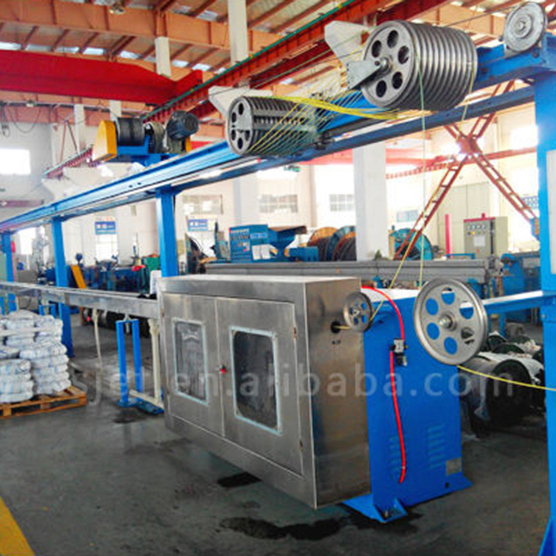
Polyvinyl Chloride (PVC) is highly heat-sensitive and presents significant processing challenges. When subjected to excessive thermal stress or high shear friction, PVC degrades rapidly. This degradation produces hydrochloric acid (HCl) gas. The release of HCl gas not only causes severe bubbling within the insulation but also actively corrodes the internal components of the extruder. Managing PVC requires equipment specifically engineered to handle its narrow processing window.
Operating a dedicated PVC cable extrusion machine provides the necessary safeguards. These machines utilize low-shear screw designs that gently melt the polymer without generating excessive frictional heat. Precise multi-zone temperature control systems ensure the barrel maintains an exact thermal profile. The barrel and screw must be constructed from corrosion-resistant alloys, such as Hastelloy or specialized nitrided steels, to withstand the acidic environment and maintain long-term operational integrity.
Polyethylene (PE) is a highly crystalline material favored for its excellent dielectric properties. However, PE is highly prone to shrinkage voids during the cooling phase. Because of its crystalline structure, PE undergoes significant volumetric contraction as it transitions from a melt to a solid. If the cooling gradient is too aggressive, the outer layer freezes instantly while the inner layer continues to contract. This differential pulls the material apart internally, creating vacuum voids.
Optimizing a PE cable extruder requires sophisticated downstream equipment. Implementing multi-stage, temperature-controlled cooling troughs is essential. Instead of plunging the hot cable directly into chilled water, the line must use a warm-to-cold water gradient. This gradual cooling process manages the crystallization rate, allowing the polymer to contract uniformly and preventing the formation of internal vacuum tears.
Cross-linked Polyethylene (XLPE) demands highly specialized processing environments. The extrusion system must manage the high pressures and temperatures required to initiate the cross-linking reaction while simultaneously venting the resulting volatile byproducts. Standard extrusion lines cannot contain the pressures necessary to keep the peroxide byproducts dissolved during the curing phase.
Deploying a purpose-built XLPE cable insulation extruder involves utilizing Continuous Vulcanization (CV) lines. These lines feature optimized curing tubes filled with high-pressure nitrogen or steam. The CV tube provides the exact heat and pressure environment needed to complete the chemical reaction without allowing bubbles to form. Specialized degassing stations and precise line-speed synchronization ensure complete byproduct diffusion, resulting in a dense, void-free insulation layer.
Low Smoke Zero Halogen (LSZH) compounds are notoriously difficult to extrude. To achieve their fire-retardant properties, these compounds contain extremely high levels of inorganic fillers, most commonly aluminum trihydrate (ATH) or magnesium hydroxide (MDH). These fillers are highly sensitive to moisture absorption and shear friction. Excessive shear causes the fillers to agglomerate, creating lumps and localized gas pockets.
Operating a specialized LSZH cable extrusion machine addresses these specific material dynamics. The equipment must feature low-compression, high-mixing screw designs that distribute the heavy fillers evenly without generating degrading friction. Robust pre-drying systems are mandatory to extract moisture from the porous fillers. Specialized crosshead designs with optimized flow channels are required to prevent filler stagnation and ensure a smooth, bubble-free surface finish.
The geometry of the extruder screw dictates the quality of the melt. Evaluating Length-to-Diameter (L/D) ratios is a primary step in upgrading equipment. Longer barrels, typically ranging from 24:1 to 30:1, provide a longer residence time for the polymer. This extended time allows for better melt homogeneity and a more gradual pressure build-up. Gradual compression systematically squeezes out trapped air back through the feed throat before the material reaches the metering zone.
Modern screw designs incorporate specialized features to enhance melt quality. Barrier flights separate the melted polymer from the un-melted solid bed, preventing solid particles from traveling down the barrel and causing surface defects. Mixing sections, such as Maddock or pineapple mixers, aggressively blend the melt to eliminate localized temperature variations and disperse additives evenly. This uniform thermal profile prevents localized gas pockets from forming due to hot spots.
Upgrading material handling systems yields immediate reductions in defect rates. Closed-loop desiccant dryers continuously monitor the dew point of the drying air, ensuring it remains low enough to pull internal moisture from hygroscopic pellets. Consistent dew point monitoring guarantees that the material entering the extruder is completely dry, regardless of ambient factory humidity.
For highly sensitive compounds, integrating vacuum systems directly into the extrusion process provides an additional layer of protection. Vacuum hoppers extract ambient air and moisture from the pellet bed just before feeding. Vented extruder barrels take this a step further. By applying a vacuum mid-way down the barrel, the system actively extracts moisture, trapped air, and volatile degradation gases directly from the polymer melt before it reaches the die head, ensuring a dense, void-free output.
The condition of the conductor wire is just as critical as the polymer melt. Bare or stranded conductors naturally carry surface moisture and ambient air into the extrusion crosshead. When the cold wire meets the 200°C polymer melt, that surface moisture instantly flashes into steam, and the trapped air expands. This reaction creates a continuous line of bubbles along the inner wall of the insulation.
Installing conductor pre-heating systems eliminates this primary source of internal bubbling. Induction or friction pre-heaters raise the temperature of the wire to match the incoming polymer melt. This process drives off all surface moisture and expands and expels trapped air from the stranded interstices before the wire enters the die. Pre-heating also improves the adhesion between the polymer and the conductor, resulting in a stronger, more uniform cable structure.
Relying on end-of-line testing allows defective cable to accumulate on the spool. Upgrading to inline defect detection systems ensures that anomalies are caught the millisecond they occur. Integrating ultrasonic wall thickness gauges and inline capacitance monitors allows operators to detect microscopic voids in real-time. These sensors measure the density and concentricity of the insulation wall, immediately flagging any variations caused by internal gas pockets.
Automated high-frequency spark testers are the ultimate safeguard against dielectric failures. Positioned immediately after the cooling trough, these testers apply a high voltage across the insulation. If a bubble or void compromises the dielectric strength, the voltage arcs through the defect, triggering an immediate alarm. This automated quality control prevents defective spools from ever reaching the customer, protecting brand reputation and reducing liability.
Purchasing off-the-shelf extrusion equipment for complex polymer compounds guarantees suboptimal results. A reliable cable extrusion machine manufacturer must operate as an engineering partner rather than a simple equipment vendor. The manufacturer must possess the capability to engineer the screw geometry and die head specifically based on your unique polymer rheology, filler content, and target production speeds. Generic screw designs cannot adequately process highly filled LSZH or heat-sensitive PVC without generating defects.
Evaluate the vendor's ability to provide a fully integrated production line. The manufacturer should seamlessly integrate upstream and downstream components—including desiccant dryers, conductor pre-heaters, multi-stage cooling troughs, and inline testing equipment—into a unified, centralized control system. A fragmented line with isolated controls leads to process instability and makes troubleshooting void formations significantly more difficult.
Never accept delivery of an extrusion line without rigorous validation. Structuring a comprehensive Factory Acceptance Testing (FAT) protocol is mandatory. The FAT must be designed specifically to test for defect rates under real-world conditions. Require the manufacturer to run your exact polymer compounds, including your specific regrind ratios and masterbatch additives, during the test.
The manufacturer must prove a zero-bubble output under continuous, high-speed operation. The FAT should also verify the seamless integration of all inline quality control systems. Test the automated spark testers, diameter gauges, and lump/neck detectors by intentionally introducing minor process variations to ensure the sensors detect and flag the anomalies accurately. This validation guarantees the equipment performs to your exact specifications before it leaves the vendor's facility.
Advanced extrusion machinery requires skilled operators to maintain defect-free production. When selecting a manufacturer, evaluate their commitment to post-installation support. The vendor should provide comprehensive on-site training for your production team, covering specific startup procedures, thermal profile adjustments, and emergency shutdown protocols. Proper training ensures your operators understand how to manipulate backpressure and cooling gradients to prevent voids.
Furthermore, establish a clear protocol for technical support and spare parts availability. Extrusion lines running aggressive compounds like LSZH or PVC will experience wear on the screw flights and die tooling over time. Partnering with a manufacturer that guarantees rapid deployment of replacement parts minimizes downtime and ensures your line continues to operate within the tight tolerances required to prevent bubble formation.
Audit your current line's temperature profiles, air gap distances, and cooling trough gradients to identify immediate mechanical misalignments.
Verify the operational status of your upstream equipment, specifically checking desiccant dryer dew points and conductor pre-heater temperatures.
Compile historical scrap data and map the exact morphology of the voids to determine if the root cause is moisture, trapped air, or thermal degradation.
Initiate technical consultations with specialized extrusion equipment manufacturers to engineer a permanent, material-specific solution for your production line.
A: Fixing bubbles requires identifying the exact source. Dry the material thoroughly using desiccant dehumidifiers to eliminate moisture. Lower barrel temperatures to prevent thermal degradation and outgassing. Ensure adequate backpressure by adjusting screen packs, and verify the extruder screw is designed to properly compress the melt and expel trapped ambient air.
A: At standard extrusion temperatures, trapped moisture instantly vaporizes into steam. This rapid expansion creates permanent gas pockets within the liquid polymer melt. These pockets become frozen as physical voids when the cable passes through the cooling trough, compromising the insulation structure and dielectric strength.
A: A PVC extruder utilizes low-shear mixing and corrosion-resistant alloys to prevent the heat-sensitive material from degrading and releasing acidic gas. An XLPE extruder requires specialized heating zones and high-pressure curing tubes to manage the chemical cross-linking process and safely vent volatile peroxide byproducts.
A: Pre-heating the bare or stranded conductor drives off surface condensation and expands trapped air within the wire strands before it enters the crosshead. This prevents the moisture and air from violently expanding when they contact the hot polymer melt, eliminating internal bubbling along the conductor wall.
A: Yes. Screen packs and breaker plates generate essential backpressure within the extruder barrel. This pressure compresses the melt and keeps residual gases dissolved. If backpressure is too low, these gases expand immediately upon exiting the die head, forming visible structural bubbles in the insulation.
A: The air gap dictates the initial cooling rate of the extruded polymer. If the gap is too short, the material suffers thermal shock in the water trough, causing the outer skin to shrink rapidly and create internal vacuum tears. Proper air gap distance ensures gradual, uniform cooling.